Topology Setup
The Two-Tier Architecture introduces a hierarchical User Plane structure, distinguishing between two kinds of UPFs:
- Edge UPFs (acting as Uplink Classifiers or UL-CLs)
- Centralized UPFs (acting as PDU Session Anchors or PSAs).
This architecture models a more realistic national-wide mobile network deployment where traffic can be routed locally or forwarded to a regional/central anchor.
graph LR
    UE([UE])
    gNB([gNB])
    EdgeUPF(["Edge UPF (UL-CL)"])
    PSA(["Centralized UPF (PSA)"])
    UE -- NR interface (closest) --> gNB
    gNB -- N3 interface (closest) --> EdgeUPF
    EdgeUPF -- N9 Interface (closest) --> PSA
Architecture Components
- Edge UPF (UL-CL): Located close to the gNBs. Aggregates traffic from multiple base stations. In this simulation, these are the "Distributed UPFs" defined in the scenario.
- Centralized UPF (PSA): Regional anchors. Each Edge UPF connects to the nearest Centralized UPF. These are defined by
num_centralized_upfs.
Configuration
To enable this mode, update your config.toml:
[simulation]
# ... other settings ...

# Architecture Configuration
scenario_mode = "two_tier"
num_centralized_upfs = 5 # Number of Centralized UPFs (PSAs) to generate
Defining Scenarios
The scenario definition remains similar to the Single-Tier mode, but the "Number of UPFs" specified in the scenario now refers to the Edge UPFs.
[countries.spain.scenarios]
# "Spain Distributed" = 52 Edge UPFs
"Spain Distributed" = 52
The simulator performs Hierarchical K-Means Clustering:
1. gNBs -> Edge UPFs: gNBs are clustered into N regions (where N is the scenario value, e.g., 52).
2. Edge UPFs -> Centralized UPFs: The locations of the Edge UPFs are then clustered into num_centralized_upfs regions (e.g., 5) to place the PSAs.
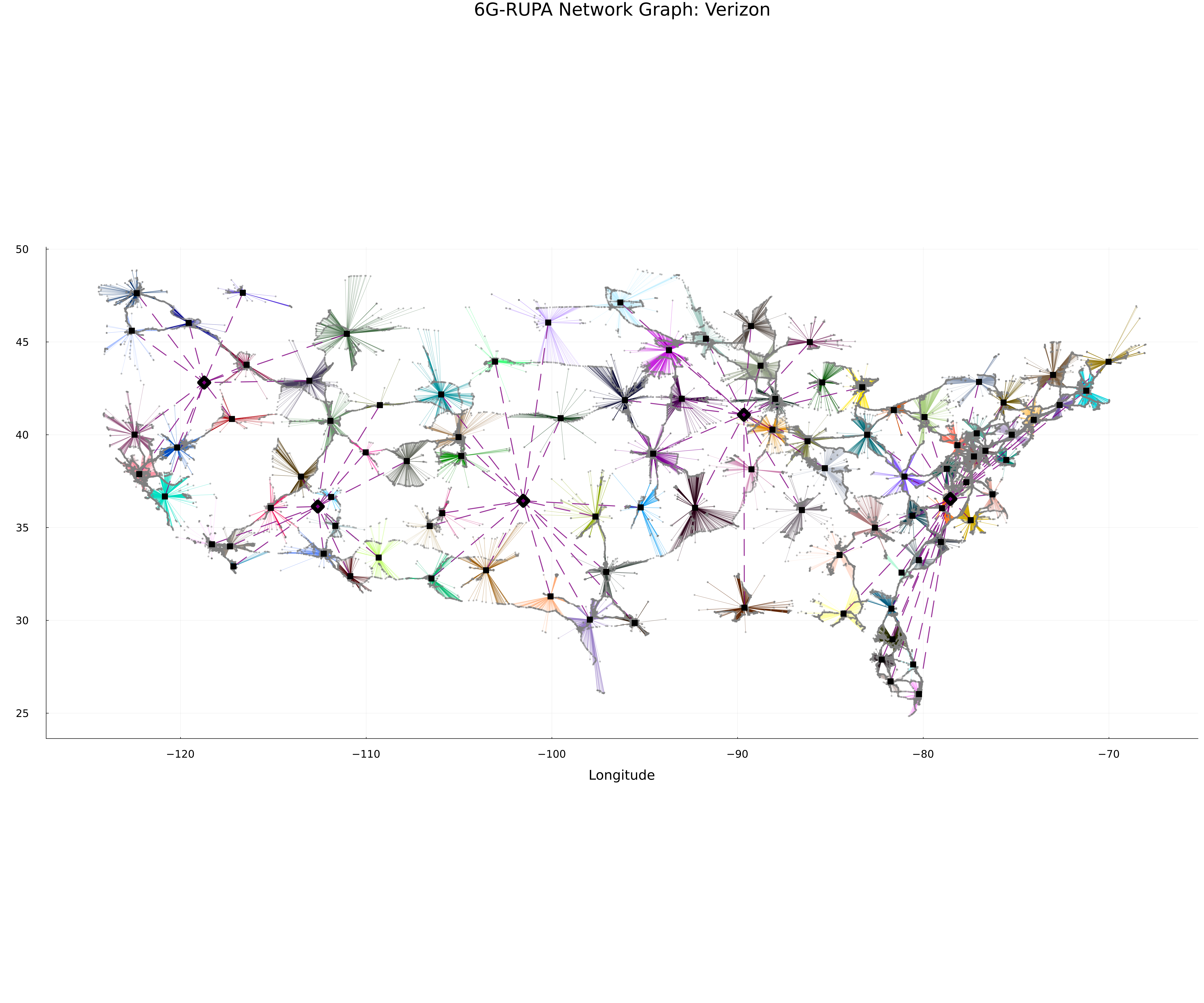
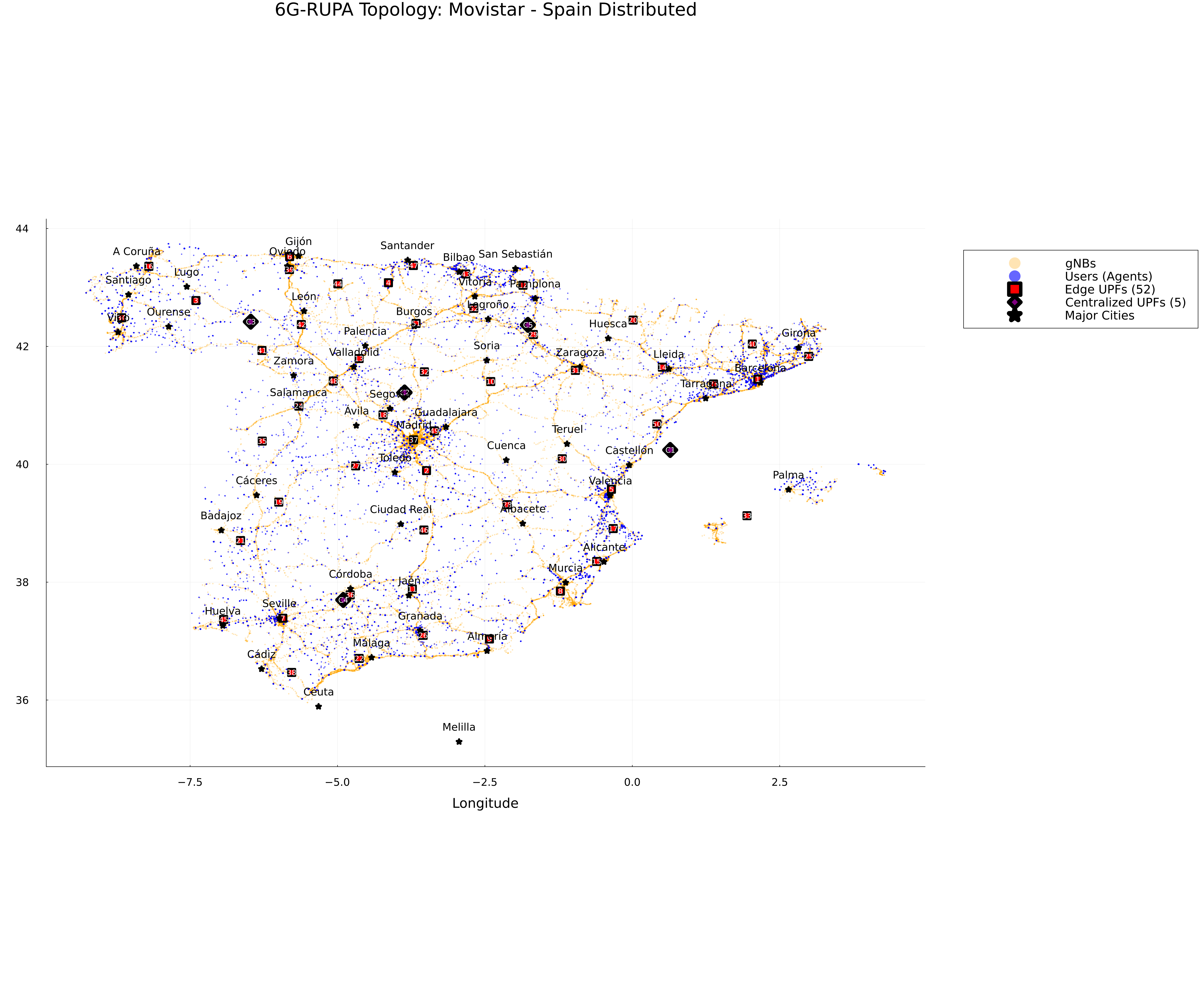
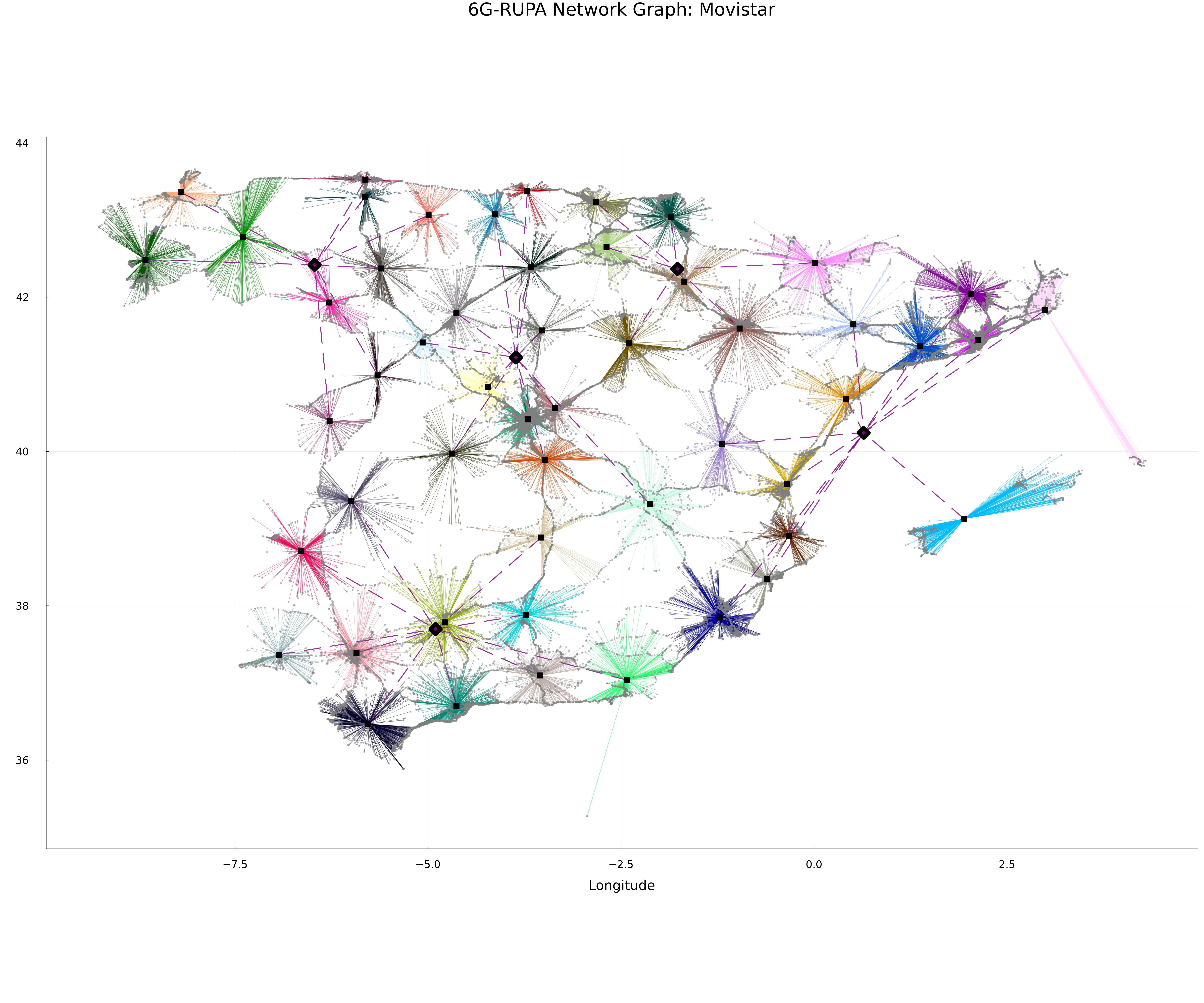
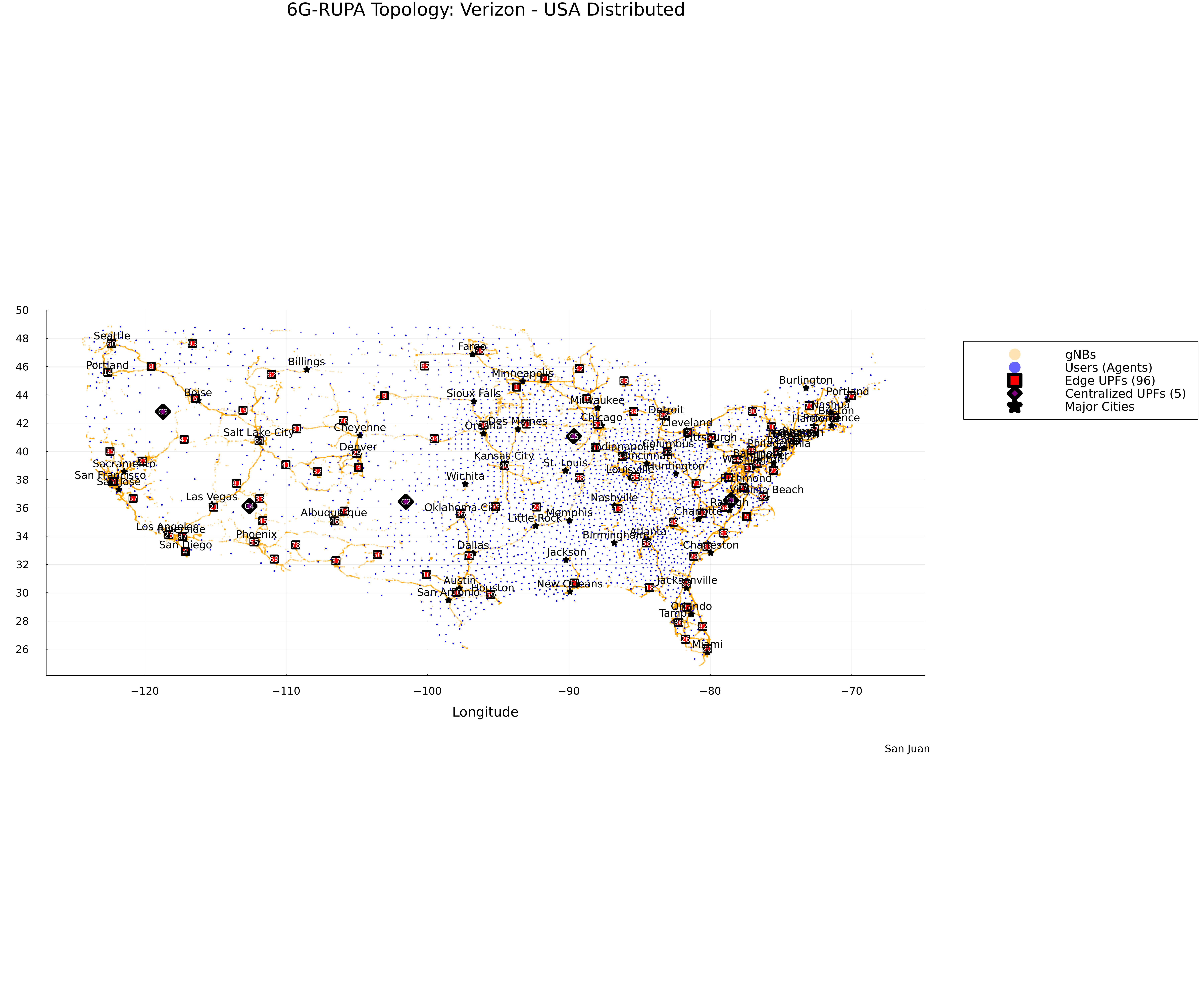
Visualization
The network graph will show two layers of UPF nodes: Edge UPFs (Black Squares) and Centralized UPFs (Purple Diamonds), connected by the N9 Interface (Purple Dashed Lines).
Topology Map
Network Graph
Topology Map
Network Graph