Topology Setup
The Single-Tier Architecture represents a network topology graph where Base Stations (gNBs) connect directly to distributed User Plane Functions (UPFs).
The elements are connected based on proximity:
graph LR
    UE([UE]) -- NR interface (closest) --> gNB[gNB]
    gNB -- N3 interface (closest) --> UPF[UPF]
UPFs are not connected to each other
In this architecture, UPFs operate independently without interconnections. Each gNB connects to its nearest UPF based on geographic proximity.
Configuration
To enable this mode, update your config.toml:
[simulation]
# ... other settings ...

# Architecture Configuration
scenario_mode = "single_tier"
Defining Scenarios
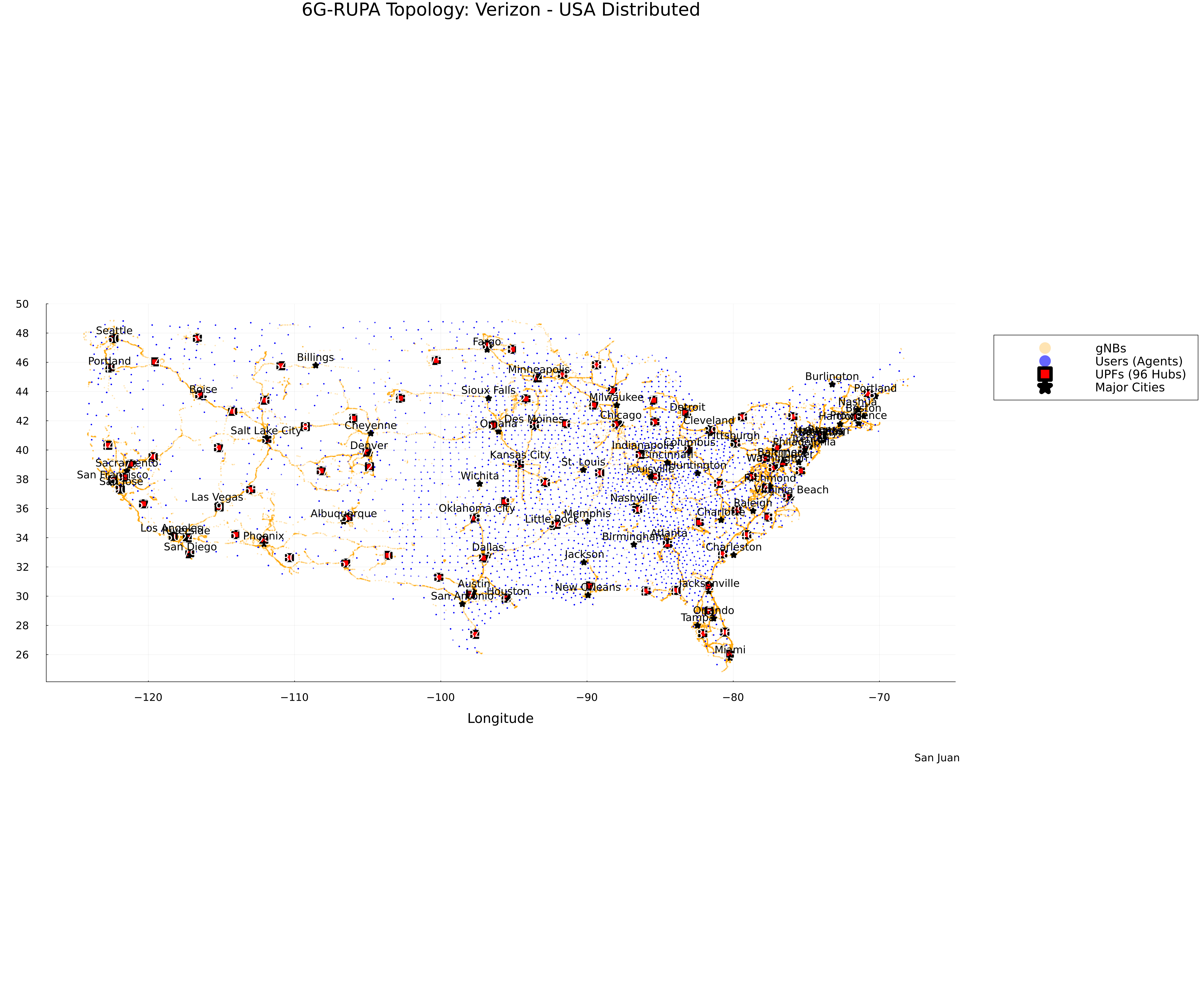
You can define multiple scenarios per country, specifying the number of UPFs to generate and spread across the country. The simulator uses K-Means clustering to optimally place these UPFs based on agent density.
[countries.spain.scenarios]
# Format: "Scenario Name" = Number of UPFs
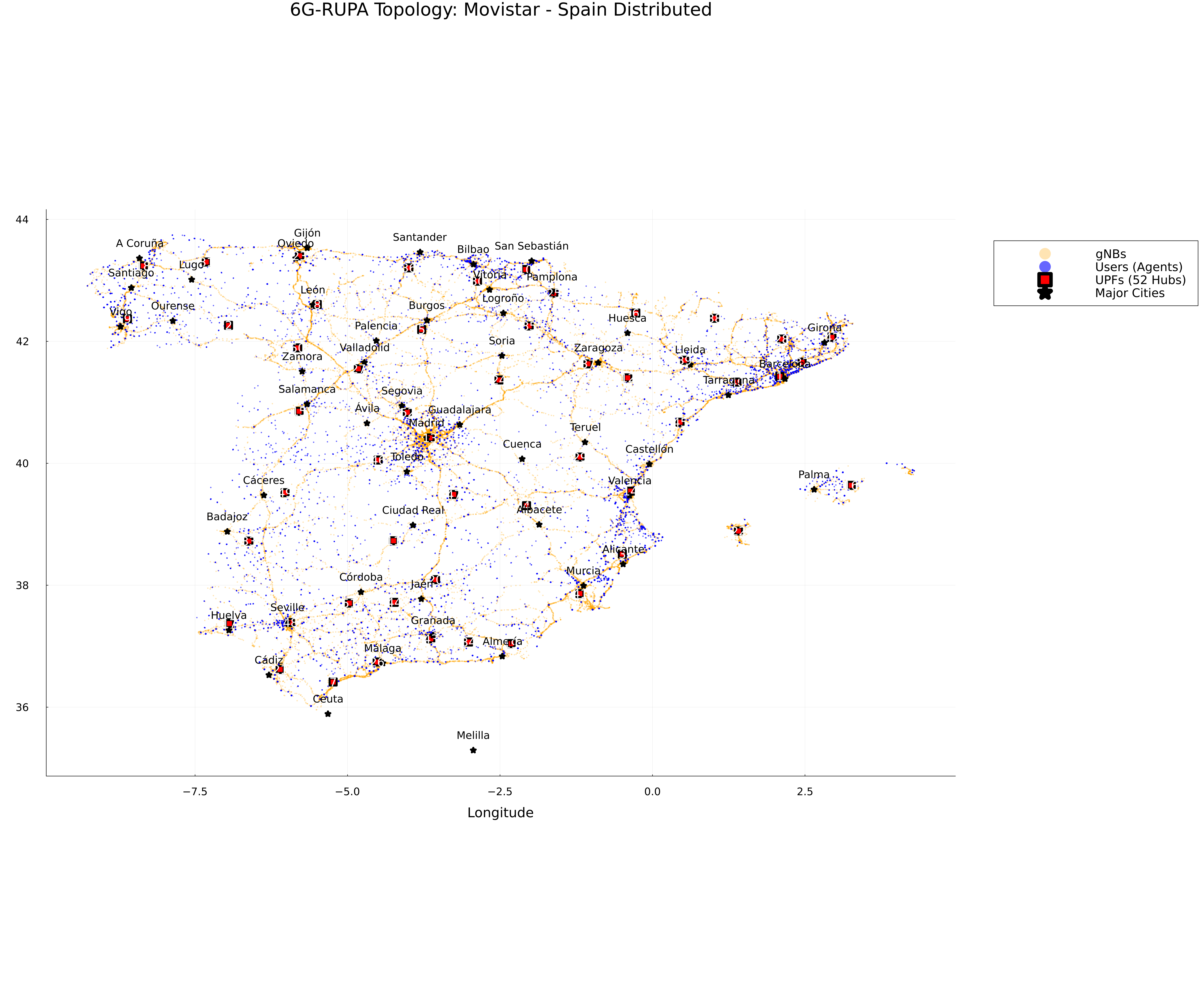
"Spain Edge" = 52 # e.g., One per province
"Spain Regional" = 17 # e.g., One per autonomous community
Visualization
When you run the simulation or the plotting script, the topology will look like this:
Topology Map
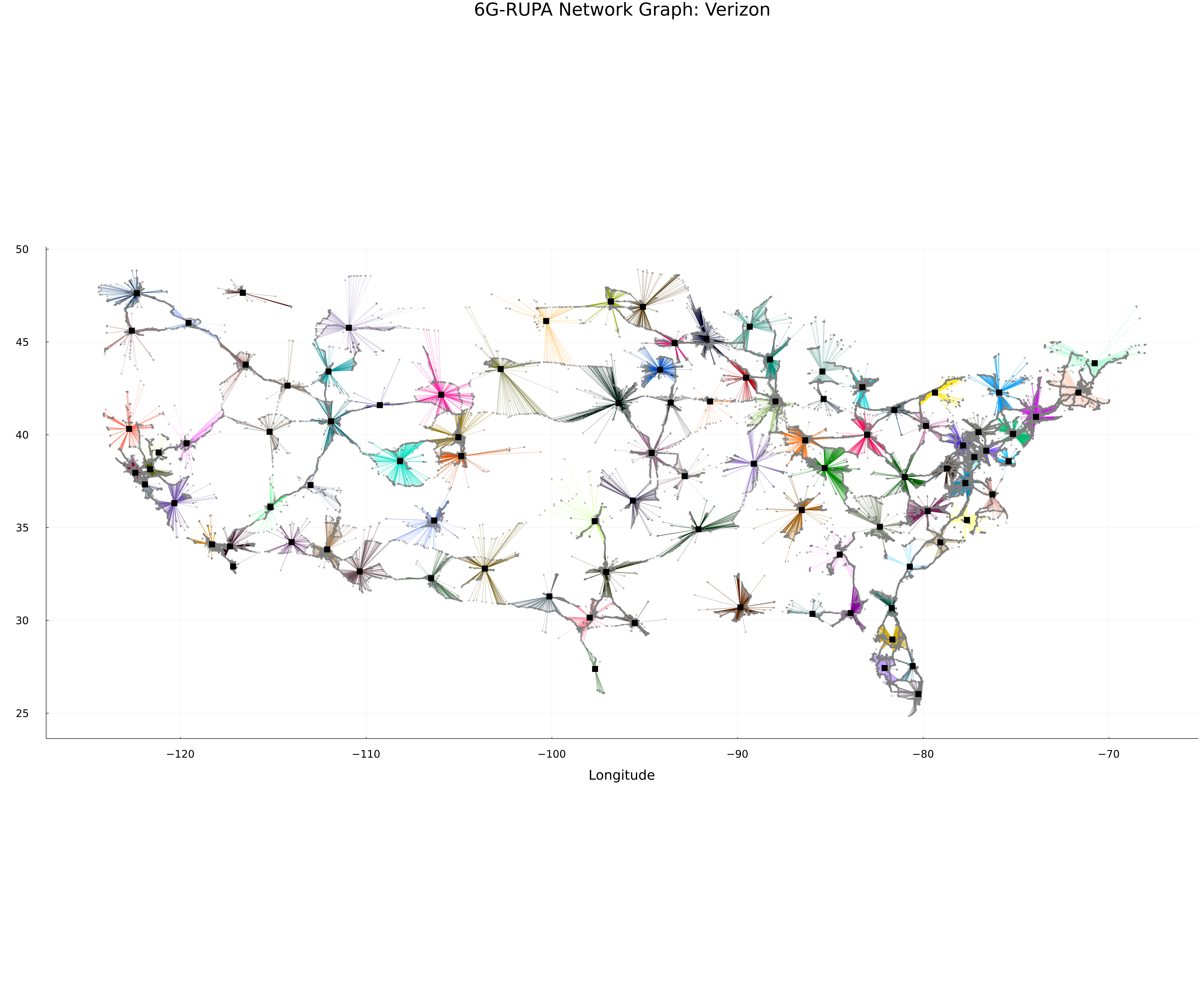
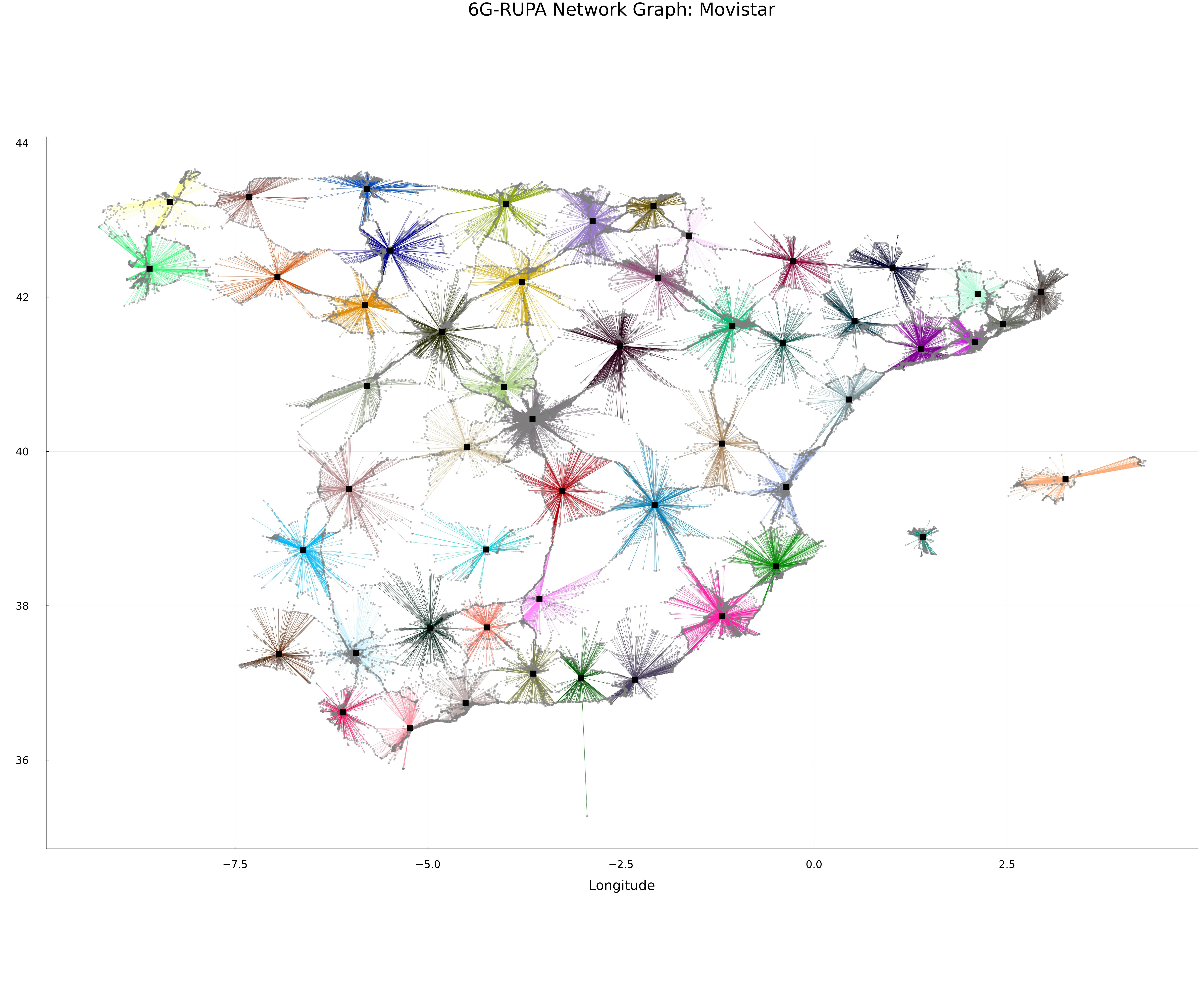
Network Graph
Topology Map
Network Graph